Introduction
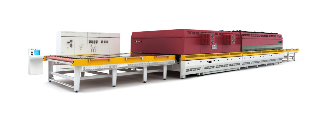
A new design of full forced convection glass tempering furnace, manufactured by Luoyang Northglass Technology Co. Ltd, has been sold by Lambert GT Ltd and installed in the UK.
This new design incorporates a total of 12 side mounted hot gas fans on the upper and lower furnace sections to recirculate the hot furnace air onto the glass surfaces thereby heating the glass by conduction of energy from a large air mass in addition to the radiant energy present within the heating chamber. This forced convection reduces the effect of any Low-E coating on the glass and therefore reduces the time required to heat the glass to a tempering temperature. The forced convection air travels through tubes closely adjacent to 72 controllable zones in the upper furnace section and 48 zones in the lower furnace section and this controllability ensures an exceptionally good uniform temperature can be established across the glass load. The system has been fitted with an optional IR line scanning camera to measure the temperature of the load. This camera installation has a compensating camera located under the roll bed to measure the uncoated side of the glass load which is used to correct the reading of the Low-E coated side.
The furnace air is recirculated by 12 inverter driven hot gas fans (total 42kW) mounted symmetrically on both sides of the upper and lower furnace sections. Pressure distribution and air flow is excellent.
Heat striping is avoided by angling the upper air tubes and elements slightly across the furnace as shown in the picture to the right. This referred to by Northglass as ‘Gapless’.
Iridescence on glass is further reduced by the use of a transverse oscillation of the quench heads and is selected manually in the quench. This is normally only used for processing thick glasses.
Bow control of glass sheets is adjusted by altering the quench head heights and these height setting are automatically saved with the glass processing recipe.
The main furnace ceramic rolls (Vesuvius) and the quench rolls are driven by rubber belts running on a double pulley system such that the belts can be changed without having to be cut or joined while on the main shaft.
The bottom elements are protected by SS plates held in place by vertical locator pins and secured by split pins.
The bottom plates and top convection tubes also act as good re-radiator surfaces providing a uniform gentle radiation and avoiding intense radiation direct from the elements when they fire at high power levels.
The quench fins are of a robust ‘Medium Efficiency’ type and each fin is fitted with an end-cap that can be removed to allow cleaning of the fin if required. Blow-back down the top surface of the glass is controlled/eliminated by a 5 element coanda plate sitting close to the glass top surface.
The quench is fitted with vertically sliding guard plates with a viewing panel at the bottom and LED lighting on the backside of the system.
The operator interface for the control system is a Windows XP computer with user friendly graphics to control the furnace.
Clicking the mouse on parts of the picture will bring up a window of the relevant settings for that section which can then be altered if required.
The top-left three yellow circles are actually count-down indicators for Heating Time, Quench Time, Cooling Time and the right-hand circle shows the Quench Fan-Speed.
The software is fitted with a sequential loading feature that allows the glass thickness of the next load to be changed while the previous thickness is still in the quench. (i.e. 10mm in the quench and 4mm on the load table and the computer will load the 4mm when there is sufficient time left for the 10mm to be cooled properly during the 4mm heating time). Due to intermittent loads arriving at the furnace this feature is not being used at the moment.
Temperature control of the 120 individual zones is carried out by separate modules that do not go through the main software control, this gives a very fast response to any change in thermocouple outputs.
There are several ‘Engineering’ screens but the information is for Northglass engineers to diagnose any faults and the screens display in Chinese. These screens will only be used by Northglass engineers and they can be accessed remotely from China if an Ethernet connection is made to the computer. The customer should make provision for an internet connection in the event that a furnace control system problem needs to be diagnosed.
System Performance
First glass was a clear glass 4mm x 1100mm x 360mm (EN 12150 test size) processed at 130 seconds heating time at 680C/680C with a quench pressure of 623 decapascals. The glass was flat and the break pattern was very good. The next glasses were 4mm Low-E glasses of the same size and came out water holding. The upper quench head was motored down 2mm and the following loads were flat with excellent break pattern.
The furnace was put into production but Kevlar marking was seen on some glasses. The Kevlar was immediately replaced on all quench rolls and the marking problem disappeared.
There is an issue at the moment in that the factory’s pre-processing equipment is not producing a good seamed edge on the glass to be tempered and it was decided that all glasses would be run slightly hot to survive the quenching.
Even with the edge-work problems the system is producing very saleable glass at the following heating rates which exceed the clear glass cycle rates quoted in the contract.
4mm Clear – 135 seconds, 92% Quench fan speed
4mm Low-E Soft Coat – 210 seconds, 94% Quench fan speed
6mm Low-E Soft Coat – 330 seconds, 48% Quench fan speed
8mm Clear – 250 seconds
10mm Clear – 350 seconds, 26% Quench fan speed. Hot Fans reduced to 10% top and 20% lower to avoid high stress levels during the early stages of heating.
These heating rates and/or furnace temperatures will be reduced when the edge-work problem has been resolved, and this will further improve the optical quality of the glass. I would recommend that the furnace is set to 670C for all glasses 4mm to 12mm and not altered for different glass thickness’s as short term temperature changes are not good for furnace stability.
General Observations
The mechanical and electrical construction of this furnace is first class. The components are from internationally recognised companies such as ABB and Siemens for motors and controllers. The quench fans are very well built, as good as anything I have seen, and vibration levels are very low at 2mm/sec at full speed.
The hot gas fans are belt driven and running extremely smoothly (almost undetectable vibration) at all speeds.
The software is graphical and intuitive
There are several novel designs on this system but one of the most interesting is the fact that the glass load indexes into the furnace at a normal index speed but when it starts to reverse, the line speed is dropped to a very very low speed and the load creeps very slowly back down the furnace. After a time the speed increases slightly (both times and speeds are operator selectable), and finally the conveyor goes to a normal line speed of around 200mm/sec as the glass heats up above the strain point. This feature, together with the hot fan speed profiles, helps reduce any marking of the glass to an absolute minimum.
Quench Booth Air Release There is considerable back pressure present on 4mm quench settings indicating that there is insufficient air release area in the booth. The furnace downstream zones reduce in temperature every time the exit door opens and this is not a good situation for stable furnace operation. The sound booth was manufactured by a company not connected to the furnace manufacturer and Peter Lambert has agreed to increase the outlet area of the booth. I would also recommend that consideration be given to cutting a hole in the floor beneath the fans so that the fans draw some air out of the booth. If this is done then there will need to be a filter to stop glass dust from being drawn up and into the fans and ultimately onto the hot glass.
Land Scanning IR Camera
The Land scanning camera is giving readings that are too high on clear glass and no sensible readings on Low-E glass indicating that the compensating camera mounted below the glass-line is not correctly compensating the reading from the top mounted line-scan camera. The Land company have been contacted, and the service engineer will return to site to correct the problem.
Recommendations
System Control Fault DiagnosisThe customer should make provision for an internet connection to the computer to be used for remote diagnosis of a fault in the event of a furnace control system problem.
Load Table: The factory is dusty and overnight the rubber covered roll are becoming coated in dust. This dust will be taken into the furnace on the underside of the glass and be deposited on the rolls. (Cement dust is incredibly abrasive and glass marking and roll surface damage will occur over time if this allowed into the furnace). It is recommended that the table should be covered when not in operation and should be wiped down before the start of production every day.
Furnace: There is a slight build up of haze on the surface of the furnace entrance end plate as a result of hot air exiting the furnace when the door is opened on each cycle. It is recommended that the end plate be wiped down when the load table is cleaned as this haze will eventually discolour the paintwork on this, currently, beautiful furnace.
Quench: Because of the poor edge-work there is considerable broken glass on the floor and in the cullet trays in the quench enclosure. It is recommended that the broken glass be cleaned out of the booth at the end of every shift. A compressed air wand should be available to help quickly clear any glass that breaks in the quench and does not drop down through the heads before the next load exits the furnace. Air release needs to be improved as discussed above.
Quench Fan Room: The quench fans are located on a platform above the quench but, despite being in an elevated position, leaves from a nearby tree were found in the fan room close to the inlets of the fans. If these leaves (or insects, moths, June bugs etc.) get through the fans they will end up in the quench heads blocking the nozzles. It is recommended that the fan inlets are fitted with close mesh drums similar as shown in the picture on the right.
Unload Table: Same as the Load table. The dust won’t affect the furnace but will get transported further down the double-glazing line until the glass is rewashed. A compressed air wand should also be located at the unload table so operators can quickly clear any glass that breaks during unloading.
Conclusion
The system is coping extremely well with full loads of vastly different size glasses, and all glasses on the bed are flat without any sign of bi-stability, saddle bow or white marking. As an example 4mm glass 1.4m x 1.4m double silver coated Low-E glasses were processed and were flat.
This furnace has to be the easiest glass tempering furnace to run that I have ever been involved with in more than 33 years.